|
パッケージ変換アダプタ
DIL44/SOIC44 ZIF-CS
|
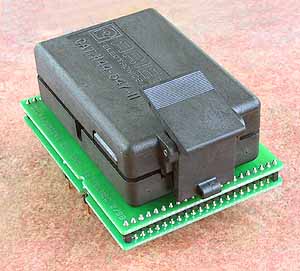 |
DIL44/SOIC44 ZIF-CS
- ユニバーサル・アダプタ - 44ピンまでの SOIC と PSOP デバイス
- SOIC gull-wing と J-lead デバイス
- ピン・リード・ピッチ 50mil (1.27mm)
- ボディー幅 150mil(3.81mm) 〜 600mil(15.24mm)
- ソケット耐用回数 - 約 20,000〜25,000回
- 注文番号: 70-0043
- ソケット: ZIF SOIC44, クラムシェル・タイプ
- ボトム: 2列, 2x 22ピン, 正方形, 0.6x0.6mm, 600mil
| |
Adapter manual
- Insert adapter to the device programmer ZIF socket according to the picture placed near of it. If you have some doubts about orientation of this adapter in device programmer ZIF socket, it is valid general rule, the orientation of the text of title is the same as the text on the top of the device programmer.
- Open the adapter ClamShell ZIF socket. Insert the device into it (place device on contacts). The right position of the programmed device in adapter ZIF socket is show at picture near (mainly left above) the adapter ZIF socket.
- Visually check interconnection between device and adapter ClamShell ZIF socket. If everything looks OK, close it and now, device is ready for programming.
- Be careful, because the incorrect insertion of adapter to the device programmer ZIF socket or device to the adapter ClamShell ZIF socket can damage the programmed device.
- To take out the device, open adapter ClamShell ZIF socket and remove device from it.
- When you finish work with adapter, remove it from the device programmer ZIF socket.
- Do not directly touch the pins of the adapter and adapter ZIF socket, because dirt may cause errors during programming of device.
- For handling with the device we recommended to use a vacuum pick up tool.
- The ZIF socket on the DIL44/SOIC44 ZIF-CS can accommodate the SOJ packages. A shim may be used for some devices to make up the difference in a device capture method between SOIC and SOJ package.
- The shim should be between 0,5mm (0.019inch) and 0,6mm (0.023inch) thick and cut to the device body width and length. It should be affixed to the inside of the cover of the socket.
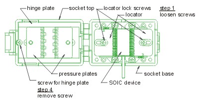
- Loosen locator lock screws.
- If you use this adapter for devices with less than 44 pins, then place device to the bottom edge of ClamShell ZIF socket. Upper contacts stay unconnected.
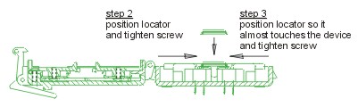
- Slide one of the locators to a position that would place the device to be tested centrally on the contacts and tighten its lock screw.
- Slide the second locator in until it almost touches the device. And tighten the locators lock screw. (Clearance is required for ease of loading and removal.)
- Remove screw for hinge plate.
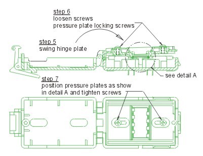
- Swing hinge plate up out of socket top.
- Loosen preassure plate locking screws and slide them out.
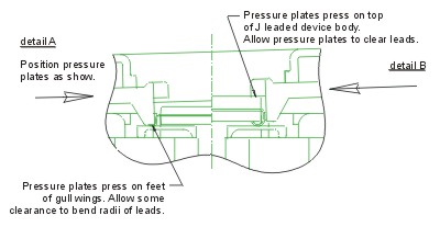
- Position preassure plates so they will press down on the feet (part of lead that gets soldered to board) of a gull wing device (see detail A), if the device has J-leads position preassure plates to press down on top of device's body (see detail B) and tighten the locking screws. It is suggested to set hinge side first.
- Swing hinge plate back into the socket top and tighten the screw for the hinge plate.
- Double check your settings.
- If programming yields isn't 100% when using programming adapter or if some unreliability appears, try to connect one 22nF-100nF multilayer capacitor (that meet the EIA X7R or Z5U specification) between leads of adapter connected to pins VCC and GND pins of programmed chip.
 対応パッケージ
 |
| SOIC8 |
 |
 |
| |
| SOIC8 |
 |
 |
| |
| SOIC14 |
 |
 |
| |
| SOIC16 |
 |
 |
| |
| SOIC18 |
 |
 |
| |
| SOIC20 |
 |
 |
| |
| SOIC24 |
 |
 |
| |
| SOIC28 |
 |
 |
| |
| SOIC28 |
 |
 |
| |
| SOIC32 |
 |
 |
| |
| SOIC40 |
 |
 |
| |
| PSOP44 |
 |
 | | |